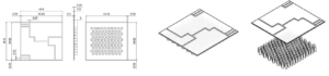
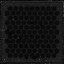
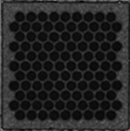
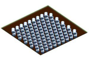
Integrated Heat Sink on AMB Substrate (Pin directly bonded AMB)
| Div. | Pin Directly Bonded AMB |
| Drawing |
 |
| Dimension |
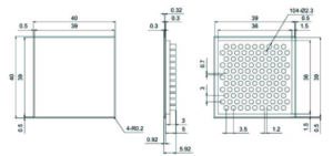
-. AMB Substrate with PIN : 44.6mm x 40.8mm x 3.92mm
-. AMB Combination : 0.3t Cu / 0.32t Si3N4 or 1.0t AlN / 0.3t Cu -. AMB Dimension : 44.6mm x 40.8mm x 0.92mm -. PIN : 98-Ø2.3 x 3mm |
| Remark |
-. Heat Spread, Miniaturization, Weight Reduction, etc.
-. Complex Bonding Solution (250W/m.K) |
Design Outline
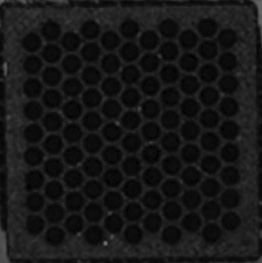
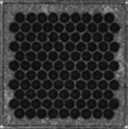
| Div. | Sintering Type | Brazing Type |
| Figure |
 |
 |
| Dimension |
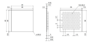
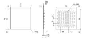
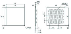
AMB: 40mm x 40mm x 0.92mm & PIN: 104-Ø2.3 x 3.0mm Combination
-. 0.4t Cu / 0.32t Si3N4 / 0.4t Cu / 3.0t Cu, 40mm x 40mm x 3.92m |
AMB : 40mm x 40mm x 0.92mm & PIN : 104-Ø2.3 x 3.0mm Combination
-. 0.4t Cu / 0.32t Si3N4 / 0.4t Cu / 3.0t Cu, 40mm x 40mm x 3.92mm |
| Pin Bonding |
Bonding Materials: Ag Sintering Paste
Bonding Condition -. Temp.: 280℃ ±20℃, Pressure : >250MPa |
Bonding Materials: AgCu Alloy
Bonding Condition -. Temp. : >780℃, Atmosphere of Reduction : H2-N2 Mixture Gas |
| Evaluation |
-. Shear Strength, Warpage
-. TST(SAT Analysis): 0,500, 1000cycles |
-. Shear Strength, Warpage
-. TST(SAT Analysis) : 0, 500, 1000cycles |
Feasibility test done with Si3N4 substrate for the comparison between sintering and brazing bonding
Test Results
Shear Strength Test

Warpage Test

Result of Thermal Shock Test (As received, 500cycles, 1000cycles)
| Div. | Sintering Type | Brazing Type | ||||
| As received | 500cycles | 1000cycles | As received | 500cycles | 1000cycles | |
|
Shear Strength
(MPa) |
66.35 | 35.99 | 32.30 | 151.51 | 85.09 | 60.33 |
|
Warpage
(mm) |
0.178 | 0.125 | 0.084 | 0.267 | 0.077 | 0.116 |
|
SAT
(C-SAM) |
OK | OK | OK | OK | OK | OK |
 |
 |
 |
 |
 |
 |
|
 |
 |
 |
 |
 |
 |
|
1. AMB Layer Material Information case study
Material Information

| No. |
Division
(Layer Thickness) |
Si3N4 T.C. (W/m·K) | Remark | |
| Sintering | Brazing | |||
| Case 1 | Case2 | |||
| 1 | Top Cu (0.3mm t) | 393 | 393 | |
| 2 | Filler (0.005mm t) | 398 | 398 | AgCu |
| 3 | Ceramic (0.32mm t) | 80 | 80 | |
| 4 | Filler (0.005mm t) | 398 | 398 | |
| 5 | Bottom Cu (0.3mm t) | 393 | 393 | Ag & AgCu |
| 6 | Filler (0.001mm t) | 100 | 398 | |
| 7 | Pin Fin Cu (3.0mm) | 393 | 393 | |
Interpretation conditions

| No. | Items | Application |
| 1 | Method | Steady state |
| 2 | Ambient Temperature | 25°C |
| 3 | Heat Information |
- SiC Die Thickness: 0.5mm
Heat Area: 10mm x10mm - Output: 400 W |
| 4 | Cooling fluid Information |
- Inlet Temperature: 25°C
- Glycol 50 - Flow Rate: 1 LMP |
2. Sintering type vs. brazing type results
Summary

<Consideration>
Sintering vs. Brazing – Equivalent Thermal Performance in Pin-Bonded AMB
Within the pin-direct-bonded AMB structure, the thermal simulation shows no signifi cant diff erence between sintering and brazing as the pin bonding method.
| Division | Max temp (°C) | Mean temp (°C) |
|
AMB with Pin Fin
(Sintering filler_0.1mm t_100W/m·K) |
172.27 | 157.73 |
|
AMB with Pin Fin
(Brazing filler_0.01mm t_393W/m·K) |
172.22 | 157.69 |
1. Review of thermal analysis according to AMB heat sink bonding method
Analytical model shape & objectives
: Review of thermal characteristics according to the Heat Sink bonding method to the AMB substrate
| AMB with Heat Sink | AMB with Pin Fin | ||
 |
Top Cu (0.3mm) |
|
Top Cu (0.3mm) |
| Si3N4 (0.32mm) | Si3N4 (0.32mm) | ||
| Bottom Cu (0.3mm) | Bottom Cu (0.3mm) | ||
| TIM (0.1mm) | Brazing Filler (0.01mm) | ||
| Heatsink Cu (5.0mm) | Pin Cu (fin 3mm) | ||
 |
 |
||
|
- Heat Sink: Base Plate 2.0mm + Pin 3.0mm ≠ 5.0mm
- TIM Contact layer: 0.1mm (100µm) |
- Pin Fin: 104-Ø2.3-3.0mm
- TIM Contact layer: 0.1mm (1µm) |
||
2. AMB Layer Material Information
Material Information
Material Information 2.0
| No. |
Division
(Layer Thickness) |
Thermal Conductivity (W/m·K) | Remark | |
| TIM | Brazing Filler | |||
| 1 | Top Cu (0.3mm t) | 387.9 | 387.9 | |
| 2 | Filler (0.005mm t) | 393 | 393 | |
| 3 | Si3N4 Substrate (0.32mm t) | 80 | 80 | |
| 4 | Filler (0.005mm t) | 393 | 393 | |
| 5 | Bottom Cu (0.3mm t) | 387.9 | 387.9 | |
| 6 | TIM & Brazing Filler (0.1mm & 0.01mm t) | 10 | 393 | |
| 7 | Heat Sink & Pin Fin (5.0mm & 3.0mm t) | 387.6 | 387.6 | |
AMB with Heat Sink
| Top Cu (0.3mm) |
| Si3N4 (0.32mm) |
| Bottom Cu (0.3mm) |
| TIM (0.1mm) |
| Heatsink Cu (5.0mm) |
AMB with Pin Fin
| Top Cu (0.3mm) |
| Si3N4 (0.32mm) |
| Bottom Cu (0.3mm) |
| Brazing Filler (0.01mm) |
| Pin Cu (fin 3mm) |
3. Interpretation Conditions
Heat Flux: 0.263W/mm²
: 39mm x 39mm_Front Copper and Assume 1:1 area

| No. | Items | Application |
| 1 | Method | Steady state |
| 2 | Ambient Temperature | 25°C |
| 3 | Heat Information |
- SiC Die Thickness: 0.5mm
- Heat Area: 39mm x39mm - Output: 0.263W |
| 4 | Cooling fluid Information |
- Inlet Temperature: 25°C
- Glycol 50 - Flow Rate: 1 LPM |


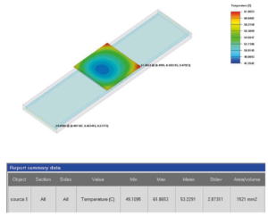
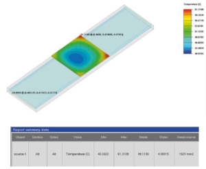
4. Thermal Analysis Result
New wpDataTable
| AMB with Heat Sink | AMB with Pin Fin |
 |
 |
|
AMB with Heat Sink
AMB Substrate + TIM 80.1mm t_10W/m·K) |
AMB with Pin Fin
AMB Substrate + Brazing Filler (0.01mm t_393W/m·K) |
5. Interpretation Result
Summary

<Consideration>
- AMB with Pin Fin has 4.1°C cooling effect better than AMB with Heat Sink
- If the SiC Die chip heat generation is High, the cooling effect is also improved
- Improvend heat dissipation characteristics in thin structures
Warpage simulation is possible on the simulation team.
| Division | Max temp (°C) | Mean temp (°C) |
|
AMB with Heat Sink
(TIM_0.1mm t_10W/m·K) |
61.9 | 53.2 |
|
AMB with Pin Fin
(Brazing Filler_0.01mm t_393W/m·K) |
61.3 | 49.1 |